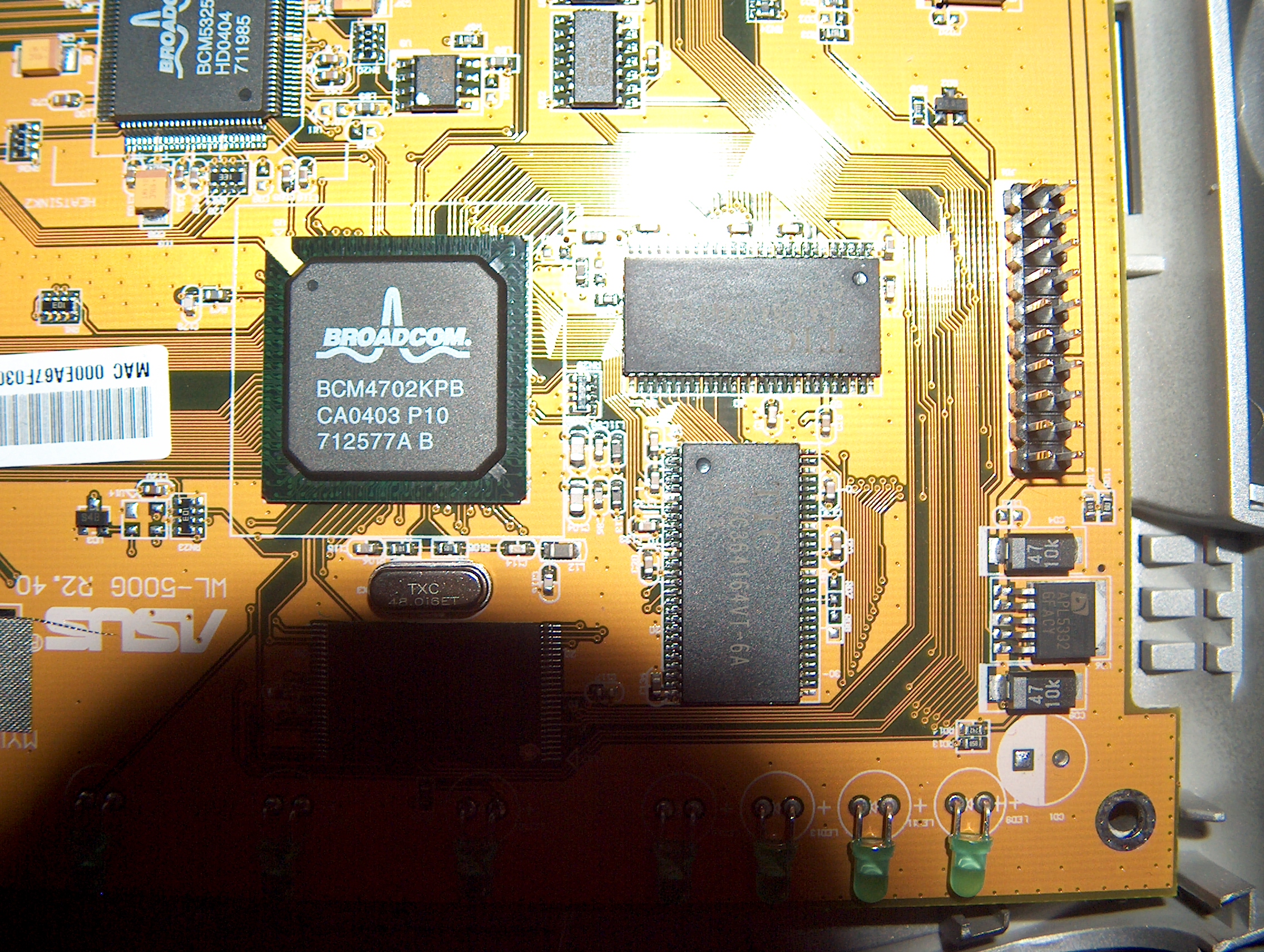
some photo's of the inside
with thanks to Meemsie (also member of this board)


 Administrator
some photo's of the inside
with thanks to Meemsie (also member of this board)
Last edited by Antiloop; 08-04-2004 at 08:41.
Administrator


with thanks to Kaloz, also note the different JTAG(?) connector (a normal one)
Last edited by Omega; 06-07-2013 at 11:48. Reason: fixed
Administrator
Mostly it's like an 1.40, but a bit cheaper in manufacturing.
http://files.wl500g.info/asus/wl500g...l%20photos.pdf
The 1.40 connector was just replaced by this header
- this is not a JTAG, but an external UART connector.
Last edited by Omega; 06-07-2013 at 12:50. Reason: fixed
Registered User
I'm showing my ignorance here, I suppose.
Anyone know if there's a stock header I could stick on that connector and hope to have some DB-9s set up to do serial I/O? My unit looks just like the one being discussed here.
Administrator
which 'one' are you talking about?Originally Posted by capouch
there are 2 different revision shown inhere with 2 different connectors...
My little Asus Collection: Too much to fit inhere, my 2 babies:WL500w 1.9.2.7-10(OLEG) VX2SE Yellow Lamborghini notebook
WL500g Forum Asus Files OpenDir
Asusforum.NL -- Asusforum.DE -- Asusforum.RU -- Asusforum.PL -- Asusforum.NET -- Asusforum.EU -- Asusforum.BE -- Asusforum.ES -- Asusforum.INFO
Registered User
The picture you refer to as the "UART header" I believe.
It is on the top of the circuit board, as opposed to on the side.
Sorry for my ambiguity.
Junior Member
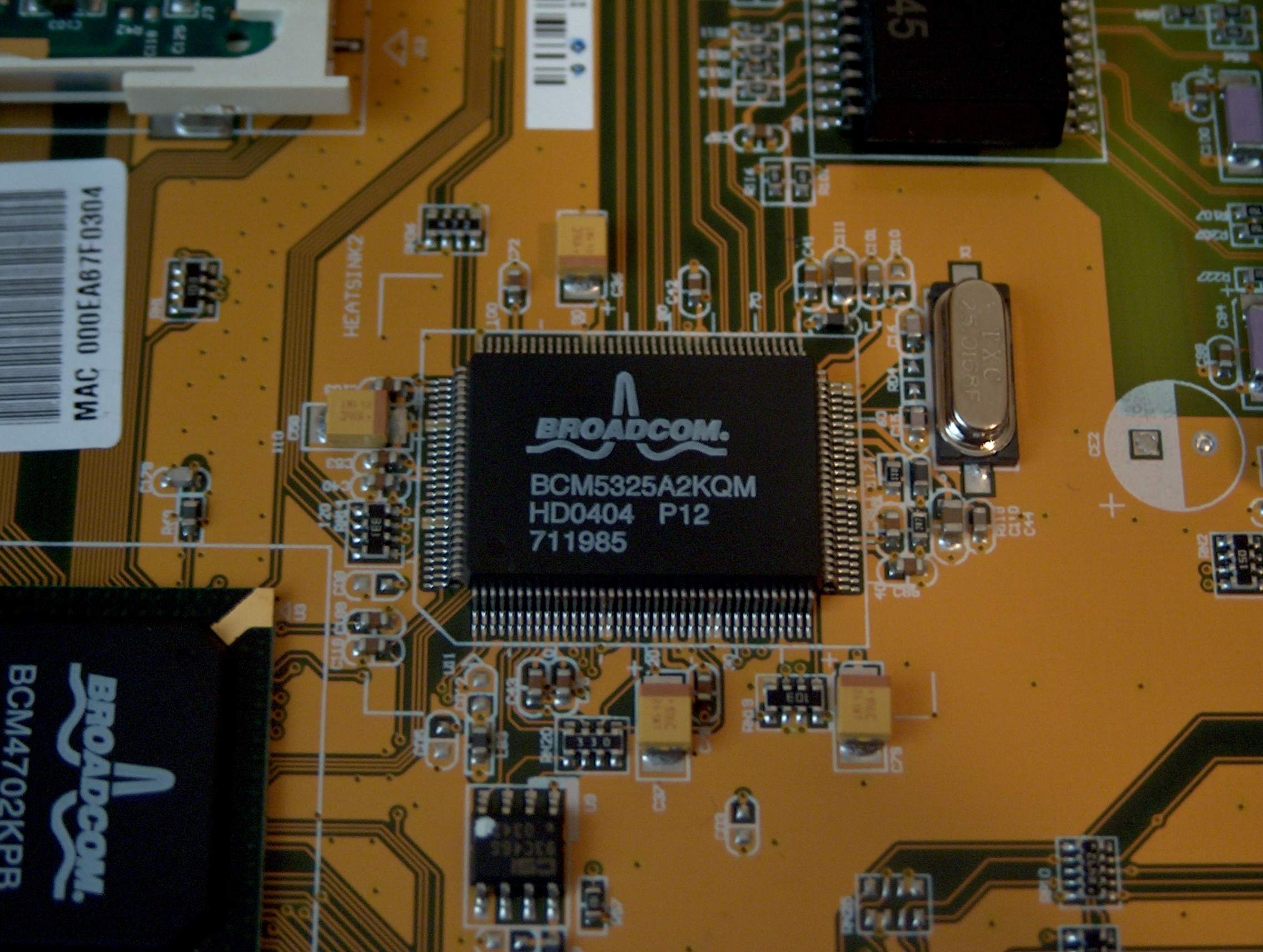
This is pictures of my wl-500g r2.40 Has ha broadcom5325

Last edited by Omega; 06-07-2013 at 13:00. Reason: fixed
Administrator
whehehe.. ít'll always be cheaper.. otherwise it will cost money to change the design...Originally posted by Oleg
Mostly it's like an 1.40, but a bit cheaper in manufacturing. The 1.40 connector was just replaced by this header - this is not a JTAG, but an external UART connector.
Junior Member
Just thinking.. the communication part of the router is on a mini-pci... i wonder what would happen if we would replace the stock mini-pci (broadcom) with an new one, containing an atheros comm-chip.. ;-)
Administrator
http://wl500g.info/showthread.php?s=...ghlight=wl500a
you should read this
Junior Member
Has anyone tried to connect a second antenna ? the MiniPCI card has only the Aux connected.. is it possible to solder a second wire to the Main connection on the MINIPCI board ?
would be quite nice to have 2 antennas especially if we wanted to have an Directional antenna + standard Omni antenna....
i also have a D-Link 624 and that device HAS 2 antennas connected to the MINIPCI...
We love modding....
Administrator
see attached, to do it easily replace it with the normal WL120g
My little Asus Collection: Too much to fit inhere, my 2 babies:WL500w 1.9.2.7-10(OLEG) VX2SE Yellow Lamborghini notebook
WL500g Forum Asus Files OpenDir
Asusforum.NL -- Asusforum.DE -- Asusforum.RU -- Asusforum.PL -- Asusforum.NET -- Asusforum.EU -- Asusforum.BE -- Asusforum.ES -- Asusforum.INFO
Financial forum supporters :)
As far as I know only one antenna from a diversity set of antenna's is used at a time.... Each packet is scanned and the antenna with the best signal receives the packet. It's like an old (el cheapo) card stereo. Have you ever stopped before a traffic light and heared noise coming out of the speakers, move the car a little bit and the signal gets better. This is exactly the same with a WiFi diversity antenna.
Also both antenna should be pointing the same direction for the best signal. (I often see AP's with one antenna to the left, and one to the right. but this is wrong.)
Registered User
Wow. Please tell me these haven't been "Photoshopped". I mean I figured she was hot, but I didn't know she was *this* hot.
Anyway, thank you for posting naked pictures of the WL500g - I'm glad I'm not the only pervert who wanted to see these.
By the way, I recommend studying these diagrams in the nude, but that's just me.
Happy holidays ;P
- Klaus
Moderator & Financial forum supporter :)
Wtf are you talking about?
These pictures are taken from a WL-500g, no big deal as Asus does not seal the casing...
 Posting Permissions

 Reply With Quote