Page 1 of 2 12 LastLast
Results 1 to 15 of 39

Thread: Exploring WL500gP hardware expansion / interfacing possibilities

Hybrid View

Previous Post Previous Post   Next Post Next Post
  1. #1

    Cool Exploring WL500gP hardware expansion / interfacing possibilities

    Wouldn’t it be nice to have a thread dedicated to hardware hacks, hardware interfacing and expansion fantasies, and the stories of our quest to turn them in to reality? As discussed in the “Upgrading WL-500g Premium, WL-500W and WL-700gE RAM to 128 MB” thread there are many such possibilities, for wl500gP and other routers as well.

    Inspired by the fact that a wl500gP with 128MB RAM can do quite some things on top of it’s base duties, and considering that the software – firmware – networking part of these is pretty well taken care of in the forum , I take the honour to inaugurate a dedicated thread to hardware upgrade – expansion – interfacing.

    Hopping to see postings on the subject of:

    * Sensors interfacing
    * Motor control
    * Robotics
    * wl500gp bus expansions
    * Interfacing to microcontrollers and custom hardware through RS232 / USB / LAN / Wi-Fi / Bluetooth / (…)
    * Interfacing to GPS modules, to smart phones, to PDA’s, to GPRS modules,to harddisks / Compact Flash's

    and in general, on upgrades and hard-hacks of any kind , I welcome us all!

    Inertial

  2. #2

    Lightbulb eeprom interface

    EEPROM interface

    1. VT6212L (usb) have eeprom interface:

    • EECS (O) - pin56
    • EECK (O) - pin55
    • EEDI (O) - pin50
    • EEDO (I) - pin49

    VT6212 specification does not mention about register to control this interface - maybe someone have any drivers that can do this?

    .................................................. .............|USB1|USB2|USB3|USB4|1+--2 _3 4


    2. BCM5325 (ethernet) eeprom interface:

    • SCK - pin7
    • SS# - pin8
    • MOSI - pin6
    • MISO - pin5

    Interesting could be to access this interface via MII interface (used by processor to configure switch). Need detailed registers description to do it.

    ...........................................{EEPROM}.........V


    FCC Doc http://pudeev.livejournal.com/26318....195278#t195278
    Last edited by Omega; 09-06-2012 at 22:37. Reason: fixed

  3. #3

    EEPROM interface

    Quote Originally Posted by mitek View Post
    EEPROM interface
    Interesting could be to access this interface via MII interface (used by processor to configure switch). Need detailed registers description to do it.
    @mitek: Thanks for the info!

    Asus WL-500b (BCM5325M) - EEPROM AT93C46 (U9 8pin)


    http://wl500g.info/showthread.php?t=5593

    Asus_WL-500_Gold_Premium_rev1.14

    Hardware

    1. BROADCOM BCM4704KPBG
    2. BROADCOM BCM5325EKQMG
    3. BROADCOM BCM4318EKFBG
    4. SPANSION S29GL064M90TFIR7
    5. HYNIX HY5DU281622ETP-5
    6. VIA VT6212L
    7. SIGE 2521A6

    PCI-ID

    • 14e4:4704 BCM4704 PCI to SB Bridge
    • 14e4:4705 BCM4704 802.11b Wireless LAN Controller
    • 14e4:4706 BCM4704 Ethernet Controller
    • 14e4:4707 BCM4704 USB Controller
    • 14e4:4708 BCM4704 Crypto Accelerator
    • 14e4:4318 BCM4318 802.11g Wireless LAN Controller
    • 14e4:4319 BCM4318 802.11a/b/g PCI Express Transceiver

    http://pci-ids.ucw.cz/read/PC/14e4

    @all:
    It seems that we need indeed registers info to proceed this way. Reverse engineering the drivers or firmware that mitek mentions (if any) in hope that they
    actually use the eeprom interface of these chips might provide a solution... I haven't spoted anything yet but haven't really looked for it that hard either.
    We would first need to spot some hardware which implements the eeprom connection with either VT6212L or BCM5325. A "Programmer's Guide" or at least
    some datasheets for the BCM4704 would be our heaven, but no such thing in sight anywhere... Does Broadcom only provides these info's under NDA's?
    Or even worst, to business partners only, under NDA's too? Do they actually make you swear to eat the hardcopy of the documents if you let any one
    else even have a glimpse on them? Seriously now, has anyone tried to approach them directly?

    Inertial

    Last edited by Omega; 22-06-2012 at 02:04. Reason: fixed

  4. #4

    Mini-PCI Type III signal names, pinouts and some specs

    Hello again!

    Let me present some info on the mini-PCI bus and the mini-PCI cards Type III, as the ones found on routers.

    The connector has 124 pins. A list of pins and signal names, adapted from PCI Local Bus Specifications Rev 2.3 and pinouts.ru follows:

    Code:
    Mini PCI Card Type III System Connector Pinout
    
    Pin Signal     Pin Signal      Pin Signal             Pin Signal 
    
      1 TIP          2 RING         63 3.3V                64 FRAME# 
        Key            Key          65 CLKRUN#             66 TRDY# 
      3 8PMJ-3       4 8PMJ-1       67 SERR#               68 STOP# 
      5 8PMJ-6       6 8PMJ-2       69 GROUND              70 3.3V 
      7 8PMJ-7       8 8PMJ-4       71 PERR#               72 DEVSEL# 
      9 8PMJ-8      10 8PMJ-5       73 C/BE[1]#            74 GROUND 
     11 LED1_GRNP   12 LED2_YELP    75 AD[14]              76 AD[15] 
     13 LED1_GRNN   14 LED2_YELN    77 GROUND              78 AD[13] 
     15 CHSGND      16 RESERVED     79 AD[12]              80 AD[11] 
     17 INTB#       18 5V           81 AD[10]              82 GROUND 
     19 3.3V        20 INTA#        83 GROUND              84 AD[09] 
     21 RESERVED    22 RESERVED     85 AD[08]              86 C/BE[0]# 
     23 GROUND      24 3.3VAUX      87 AD[07]              88 3.3V 
     25 CLK         26 RST#         89 3.3V                90 AD[06] 
     27 GROUND      28 3.3V         91 AD[05]              92 AD[04] 
     29 REQ#        30 GNT#         93 RESERVED            94 AD[02] 
     31 3.3V        32 GROUND       95 AD[03]              96 AD[00] 
     33 AD[31]      34 PME#         97 5V                  98 RESERVED_WIP 
     35 AD[29]      36 RESERVED     99 AD[01]             100 RESERVED_WIP 
     37 GROUND      38 AD[30]      101 GROUND             102 GROUND 
     39 AD[27]      40 3.3V        103 AC_SYNC            104 M66EN 
     41 AD[25]      42 AD[28]      105 AC_SDATA_IN        106 AC_SDATA_OUT 
     43 RESERVED    44 AD[26]      107 AC_BIT_CLK         108 AC_CODEC_ID0# 
     45 C/BE[3]#    46 AD[24]      109 AC_CODEC_ID1#      110 AC_RESET# 
     47 AD[23]      48 IDSEL       111 MOD_AUDIO_MON      112 RESERVED 
     49 GROUND      50 GROUND      113 AUDIO_GND          114 GROUND 
     51 AD[21]      52 AD[22]      115 SYS_AUDIO_OUT      116 SYS_AUDIO_IN 
     53 AD[19]      54 AD[20]      117 SYS_AUDIO_OUT GND  118 SYS_AUDIO_IN GND
     55 GROUND      56 PAR         119 AUDIO_GND          120 AUDIO_GND 
     57 AD[17]      58 AD[18]      121 RESERVED           122 MPCIACT# 
     59 C/BE[2]#    60 AD[16]      123 VCC5VA             124 3.3VAUX     
     61 IRDY#       62 GROUND     
    
    8PMJ = 8 position modular jack connector pin (RJ45)

    To help things some more, an image of the actual wi-fi card used in the wl500gP, overlayed with pin numbers and signal names is attached bellow.

    Some mechanical specs for type III connectors (adapted from the PCI Local Bus Specifications Rev 2.3) where found and are attached bellow too.

    While having a look at the mainboards of wl700gE and wl500W, I noticed two interresting things:

    The wl500W seems to have pads for a 68 pins pcb connector(!) on the underside of the mainboard (Bottom Layer). From a quick look i had, it seems that most of the interesting signals of the mini-PCI bus are present there . Initially i hopped they where EBI signals (Expansion Bus Interface) but no luck...

    Wl700gE seems to have pads for a type III mini-PCI connector!


    I am currently fighting my way through the PCI Local Bus Specs. Maybe an easier way (?) to approach things would be a PCI-to-PCI Bridge on a mini-PCI card (if such thing exists). This could be used in order to connect a multitude of Mini-PCI cards. I still dont understand all about how PCI's work, and reserve the right to return on the subject after completing my reading...


    Inertial
    Attached Images Attached Images    

  5. #5

    Mini-PCI type III connector pads on wl700gE board

    I managed to find a detailed enough picture of the underside of wl700gE mainboard, here in the forum.

    82 connected pads out of the 124 on the wl700gE mainboard as opposed to 86 connected pads on the wl120v2, but still it yields a match!
    These are indeed pads for a mini-PCI type III connector
    Actually, four Reserved pins are left Non Connected at wl700gE as opposed to the WL120V2 wifi card.

    Things must be a bit crowded at the PCI bus of wl700gE, between IDE controllers, USB 2.0 Hosts and onboard wifi's. Maybe the IDE controller is on the EBI bus, I will get hold of a wl700gE for a while, that will give me the chance to have a closer look... The wl700gE will be on short loan though, no chances for hardware experimentations... Whether it's possible to connect a mini-PCI connector and a type III card and make it visible for the firmware, i know not. I had a quick read through the firmware's source code of pci.c and such, i can't really say... I could probably use some help on that one.

    Here goes the picture overlayed with pin numbers and signal names.

    Inertial
    Attached Images Attached Images  

  6. #6

    Current consumption measurements on Asus WL500gP

    In order to remove the uncertainty around the current consumption levels of the various usb peripherals that may be connected on a wl500gP (modified with extra USB ports or just plain, straight out of the box), an experimental current measurement set up was used.


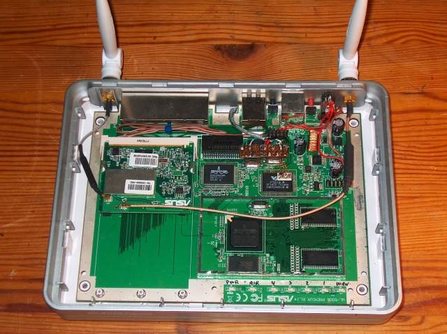
    The router was supplied with power through a digital millimetre, set at 10 Amps range, then the current consumption of various configurations of hardware was measured. The peek current during power-on of each module was also recorded. The router was modified with 128MB RAM, MAX202 RS-232 dual transceiver, two extra USB ports (taken from VIA chip). Firmware: Oleg's ver. 1.9.2.7-9. Picures of the mods here


    Current Measurement During Boot Sequence:

    Set up:
    Two lan ports connected with PC's
    Serial port 0 console connection to the unit
    Wi-Fi initially off
    No usb devices connected

    Result:

    Starts at 0.67 Amps for a couple of sec’s, then 0.89 Amps then ranges between 0.85 to 1.05 Amps and then after boot sequence and os-startup is complete stabilizes at 1.00 Amp.

    Now we are just at the first prompt after the boot sequence.


    Removing one of the two Lan cables dropped the current to 0.95 Amps
    Connecting a 1GB flash USB rises at 1.04 (90mA more)
    Connecting a 4GB flash USB rises at 1.13 (90mA more)
    Connecting a 64MB flash USB rises at 1.18 (50mA more)


    Connecting these results on the following messages on the Serial Console:

    Code:
    echo for PaN ::: &&&PaN
    hub.c: new USB device 01:03.2-2, assigned address 2
    usb.c: USB device 2 (vend/prod 0x19b6/0x1024) is not claimed by any active drive
    r.
    hub.c: new USB device 01:03.2-1, assigned address 3
    usb.c: USB device 3 (vend/prod 0x90c/0x1000) is not claimed by any active driver
    .
    hub.c: new USB device 01:03.1-2, assigned address 2
    usb.c: USB device 2 (vend/prod 0x1043/0x8006) is not claimed by any active drive
    r.
    
    / #
    Please note that the firmware was set up not to mount the USB mass strorage devices upon detection, in order to see if there is any difference in consumption pre-mount and post-mount. So let's mount them manually:


    Code:
    / # insmod scsi_mod
    SCSI subsystem driver Revision: 1.00
    / # insmod sd_mod
    / # insmod usb-storage
    That's part of what we get at the Serial Console:


    Code:
    usb.c: registered new driver usb-storage
    scsi0 : SCSI emulation for USB Mass Storage devices
      Vendor: takeMS    Model: USB Easy          Rev: 1100
      Type:   Direct-Access                      ANSI SCSI revision: 02
    Attached scsi removable disk sda at scsi0, channel 0, id 0, lun 0
    SCSI device sda: 7864320 512-byte hdwr sectors (4027 MB)
    sda: Write Protect is off
     /dev/scsi/host0/bus0/target0/lun0: p1
    scsi1 : SCSI emulation for USB Mass Storage devices
      Vendor: S3+       Model:                   Rev: 8.07
      Type:   Direct-Access                      ANSI SCSI revision: 02
    Attached scsi removable disk sdb at scsi1, channel 0, id 0, lun 0
    SCSI device sdb: 1918976 512-byte hdwr sectors (983 MB)
    sdb: Write Protect is off
     /dev/scsi/host1/bus0/target0/lun0: p1
    scsi2 : SCSI emulation for USB Mass Storage devices
      Vendor: Generic   Model: USB Flash Drive   Rev: %z!Y
      Type:   Direct-Access                      ANSI SCSI revision: 02
    Attached scsi removable disk sdc at scsi2, channel 0, id 0, lun 0
    SCSI device sdc: 128512 512-byte hdwr sectors (66 MB)
    sdc: Write Protect is off
     /dev/scsi/host2/bus0/target0/lun0: p1
    USB Mass Storage support registered.
    Let's check the mounted devices:

    Code:
    / # df
    Filesystem           1k-blocks      Used Available Use% Mounted on
    /dev/root                 3008      3008         0 100% /
    Mounting the usb's:

    Code:
    / # mkdir /tmp/hd1
    / # mkdir /tmp/hd2
    / # mkdir /tmp/hd3
    / # mount /dev/discs/disc0/part1 /tmp/hd1
    / # mount /dev/discs/disc1/part1 /tmp/hd2
    / # mount /dev/discs/disc2/part1 /tmp/hd3
    / # df
    Filesystem           1k-blocks      Used Available Use% Mounted on
    /dev/root                 3008      3008         0 100% /
    /dev/discs/disc0/part1   3924460   1103812   2820648  28% /tmp/hd1
    /dev/discs/disc1/part1    959200    703104    256096  73% /tmp/hd2
    /dev/discs/disc2/part1     61596      4494     57102   7% /tmp/hd3
    / #
    Everything remains at 1.18 Amps... So no difference when the Flash memory usb's are connected, whether mounted or not.

    Let's turn on wi-fi:

    Code:
    / # wl radio on
    / #
    Now it's up to 1.43 Amps (250mA more)(TX Power settings are the default, mini-PCI card is the original WL120G R1.01)


    Connecting a multi-card reader loaded with a 2GB CF:

    That's 1.58 Amps after a peak of 1.60

    Code:
    / # hub.c: new USB device 01:03.2-3, assigned address 6
    
    / # mkdir /tmp/hd4
    / # mount /dev/discs/disc4/part1 /tmp/hd5
    / # df
    Filesystem           1k-blocks      Used Available Use% Mounted on
    /dev/root                 3008      3008         0 100% /
    /dev/discs/disc0/part1   3924460   1103812   2820648  28% /tmp/hd1
    /dev/discs/disc1/part1    959200    703104    256096  73% /tmp/hd2
    /dev/discs/disc2/part1     61596      4494     57102   7% /tmp/hd3
    /dev/discs/disc4/part1   2000064   1706400    293664  85% /tmp/hd4
    / #
    Connecting two more Lan's: 1.70 Amps (100mA more)


    Initiating a large file transfer between two pc's connected over lan through the wl500gp doesn't affect current consumption which remains 1.70Amps

    Disconnecting all usb flash memory devices, leaving only one lan connection, Wi-fi, and the RS-232 console too: 1.18Amps (520mA less)

    Wi-fi turned off: 0.92Amps (260mA less) (It was 250mA up when turned on, but that's the reading i got)

    Now to the interesting part:

    60 GB, 2.5'' IDE HD connected through e-quip IDE to USB adaptor, power supplied from usb: 1.45Amps during several spin-up seconds then 1.25 Amps (530mA peek, 330 there after)

    Disconnecting the usb-HD, connecting an external one:

    250GB 3.5'' maxtor external HD, externally supplied: 1.02 Amps, no peek observed. (100 mA more)


    I also checked the re-settable poly-fuses (on the mainboard) used to protect the router from USB overcurrent and they are rated 0.750 mA. I checked their specs from their manufacturer and it turns out they trip at 1.5 Amps(!), not that i would recommend connecting anything that heavy though.
    So as thing are connected now on the modded router, three usb devices are supplied from the power initially intended for one of the two original usb ports while the other get's all the current by itself.


    I had to stop experimenting at that time, but still want to take measurements during file transfers from/to the Flash memory devices and the usb-HD. These are sure to draw more current, how much exactly remains to be measured...


    To sum it up, here are the same results, presented in a table:


    Code:
    Device/Action:                      Current            Peek Current
                                        Consumption:       Consumption:
    
    Asus WL500gP start-up (+2 Lan)         670 mA               -
    Asus WL500gP boot (+2 Lan)          850 - 1050 mA         1050 mA
    Lan connected (each)                    50 mA               -
    1GB iStar, usb Flash memory             90 mA               90 mA
    4GB takeMS, usb Flash memory            90 mA               90 mA
    64MB, usb Flash memory                  50 mA               50 mA
    usb multi-card reader with 2GB CF      150 mA              170 mA
    Asus wl-121 mini-PCI power-on          250 mA               -
    2.5'' IDE HD - USB (internal)          330 mA              530 mA
    3.5'' IDE HD - USB (external)          100 mA               -
    Also note that the usb ports will try to provide as much current as possible and the poly-fuses protecting them will only trip somewhere in the region 1Amp - 1.5Amps (guess not tested) (usb protecting Poly-fuses marked "P.075", WL500gP board version R1.14). There is also the Poly-fuse protecting the main power supply, (Main Poly-fuse marked "P.260", WL500gP board version R1.14). In general poly-fuses trip, when the current exceeds by some percentage their rating and then, once the overcurrent condition has been removed, conduct again when they have cool down.


    I hope this info may be useful somehow

    Greetings to all


    Inertial


    Attached: 1) The measurements set up. 2) Cable connections (little cables usb mod supply, larger cables router supply)
    Attached Images Attached Images   
    Last edited by Inertial; 28-04-2008 at 12:46.

  7. #7

    RS232 serial ports - max202 TTL-RS232 signal level translation

    Following some posts in the forum on the RS232 port subject, a dual RS232 line transceiver was implemented, based on a 5-Volt, max202, narrow-SOIC 16pin chip. Spec's say that anything below 0.8 Volts is perceived as Low-Level signal whereas anything above 2 volts is perceived as High-Level signal so the 3.3 volts from the board are definitively interpreted correctly as a High-Level. Supply-voltage-wise the requirements range between 4.5 to 5.5 volts, so the on-board regulated USB supply kindly donates the appropriate voltage (and a maximum current of 15mA), keeping everyone happy. MAX202 is oriented towards battery operated, handheld applications, and only needs five 100nF capacitors to operate. Using smd ceramic capacitors results in a very small sized pcb. The transceiver circuit was tested OK using a USB to RS-232 converter and a plain-old RS-232 port (still quite a few of those available around).

    The default settings for connection to the WL500gP over RS-232 are 115200 Baud rate, 8 Data bits, No Parity, 1 Stop bits, No Flow Control.

    Port 0 is console, port 1 is free to use, both are found on /dev/tts/

    Code:
    echo "Hello Network" >> /dev/tss/1
    will sent a string to rs-232 port one.


    Note: FTDI based USB to RS232 converters work fine with Oleg's firmware ver. 1.9.2.7-9. and provide connection for extra micro-controllers if need be.


    I will update this post with schematics / more details / better pic's and hopefully in the later future with a small pcb design.

    Visible in the photo is the unorthodox use of an old prototyping board with tracks split in two, and some smd capacitors mounted in equally unorthodox orientations. that wasn't rapid prototyping, but rather impulse prototyping . It also made me consider a small custom pcb in the future.


    Greetings

    Inertial
    Attached Images Attached Images  

  8. #8
    A bit of a different USB implementation.
    The principle is the same - in a way, that goal was to enable the two unused USB ports on the router - with maximum tidyness and serviceability in focus. Clicking on picture brings up bigger image.
    Last edited by Oyabun; 28-04-2008 at 11:57. Reason: resized picture

  9. #9

    Talking Additional USB ports mod refinement

    Hello again!

    Following the post "Additional USB ports and Internal HD!" by parper, I decided to add two more USB ports by soldering tiny wires on the pins of the VIA (VT6212L) chip. I used very thin veneer-insulated copper wire taken from the coil windings of a Cathode Ray Tube (CRT) of an old monitor. I had a bit of a trouble finding the correct circuit schematic and component values on the forum or the net (I failed to actually), so I examined the wiring of the existing USB ports and used a multimeter to figure these out. The findings are: Each one of the data pins (usb3D+,usb3D-,usb4D+,usb4D-) is tied to ground by an 15K ohm resistor and filtered in pairs using magnetically coupled inductors. Power supply and grounding are also filtered by inductors and capacitors. The configuration I finally went with is: four 15K ohm resistors tying the usb data pins to ground, and some simple LC (inductor capacitor) filter for the positive power supply. Having trouble to locate suitable smd resistors in the "junk pile", pairs of 10K ohm and 4k7 ohm resistors off an old ink-jet printer board were used in series. The 100nf ceramic disc capacitors and ferrite beads for the supply filter were kindly provided by the same old monitor as before.

    A standard dual stacked type A female pcb connector was "slightly" modified and the end result is quite acceptable. The case is also modified, with a rectangular hole between the WAN and LAN1 connectors, to house the usb connector.

    In details, the usb connector was fitted with an eight pin standard 2.54 cm pitch gold plated male connector, while the rest of the circuit (pull-ups and filters) was attached to it’s respective female connector. The usb connector is not attached to the wl500gp PCB, and it’s only held in place by the metallic springs on the top and bottom of it’s body, holding against the rectangular opening on the case.

    I have later refined the USB mod. This was needed since I already had managed to remove most of the fine wires while accidentally pulling the resistor – filters pcb. Oyabun is right: the previous implementation of mine was a little mess! Electrical connections are now achieved using a very small piece of pcb, with a fine pitch 1mm, gold contact, female connector, attached to the asus mainboard with Devcon - high strength "plastic steel epoxy". I have to admit it looks really neater! This way things are a bit more modular too, which comes handy since I plan to design and etch a small pcb to house the pull-ups and the filters, all hopefully in smd sizes. When successful, all results schematics, pcb layouts and relative photos will be posted here


    Happy modding!

    Inertial


    Bellow are some pictures, one during the fabrication of the small pcb (included for it's strange beauty and it's mild industrial after-taste), and two more of it as it looks on the board. The little wires were not soldered on it yet; since it took 24 hours waiting for the epoxy to fully cure. The last picture shows the final arrangment with the little (fragile) wires in place.
    Attached Images Attached Images    
    Last edited by Inertial; 28-04-2008 at 14:53.

  10. #10
    Join Date
    Dec 2007
    Location
    The Netherlands - Eindhoven
    Posts
    1,767
    wow this is cool stuff
    I never really attempted to open my box up... I dont like to break the warranty
    verry nice pictures, but some Soldering might be done a bit more cleaner
    and no, I'm not really good myself at soldering

  11. #11

    Smile It has been there since the beginning - UUP's sighting!

    Well these wonderful pads of what seems to be an 8-pin ic, where there, next to the flash chip, on all wl500gP's, wl500w's and wl700gE's, waiting to be noticed...

    What that IC might have been remains unclear...

    If it was a real time clock, wouldn't it need a back-up battery? most probably yes.

    An eeprom then...? but what it's use would be...?

    Or do they give access to some internal pins of nearby chips...? Probably not since test points or connector awaiting pads would have been used in that case...

    It seems (a wild guess) that there might be the signals of an I2C or an SPI presented there...

    Having zero spare time now, it will take a while before I could have a chance to investigate this matter further...

    The pads are know to belong to an IC nicknamed U12

    If you can shed light on this case... we want to hear from you

    Inertial

    Bellow is a picture of the UUP's (Unidentified Unsoldered Pads) in question...
    Attached Images Attached Images  

  12. #12
    Join Date
    Dec 2007
    Location
    The Netherlands - Eindhoven
    Posts
    1,767
    Quote Originally Posted by Inertial View Post
    If it was a real time clock, wouldn't it need a back-up battery? most probably yes.
    the routers don''t have any, they update the time from the internet remember

    anyway, about what are you talking? about those pieces of metal with a white box left top?

  13. #13

    Question UUP chip U12 - maybe JTAG?

    So U12 is on several wl-models?? Hmmm... I think they are JTAG pads.

    Anybody with some knowledge/testing ability of JTAG, can have/borrow a bricked wl500gP from me.


    http://www.3iii.dk/wifi/asus.htm Please email me at wl500gp@3iii.dk
    Last edited by Omega; 09-06-2012 at 23:36. Reason: fixed

  14. #14
    I have been looking with some interest through the threads on adding RS-232 support regarding the connection to built-in UART.
    What I'm looking for actually is not RS-232, but RS-485.

    Why? For implementing DMX/RDM protocol for control of stage lighting units. Actually it has already been done by using USB-DMX controller such as Enttec OpenDMX.
    But to do it directly with built-in UART would be far simpler and cheaper.

    I would like to connect RS-485 transciever, or ideally two RS-485 transceivers, if indeed both UARTs can be used simultaneously. Example would be SN75176B
    if unisolated, or actually I have some very nice fully isolated Maxim transceivers around too. This would make possible control of up to 1024 DMX channels.

    Before I open up the case of the WL-500gP I wonder about the software aspects first though. Is it possible to set bit rate at 250kbps, 2 stop bits, no parity?
    How to control Tx/Rx mode for the transceiver? Any ideas on this?

    I found this link to datasheet for VT6212L: http://wl500g.info/attachment.php?at...2&d=1209754575

    http://down.chinaeda.cn/upload/2007_...1218477472.pdf Maybe some useful information in there.
    Last edited by Omega; 20-06-2012 at 10:08. Reason: fixed

  15. #15
    Join Date
    Dec 2007
    Location
    The Netherlands - Eindhoven
    Posts
    1,767
    Quote Originally Posted by snarfer View Post
    I found this link to datasheet for VT6212L:

    http://down.chinaeda.cn/upload/2007_...1218477472.pdf

    Maybe some useful information in there.
    nice
    but doesnt that just add nothing to what we already know, the chip has 4 usb ports...

Page 1 of 2 12 LastLast

Similar Threads

  1. speedtouch 546 + wl500gp
    By kitkatneko in forum WL-500gP Q&A
    Replies: 2
    Last Post: 22-10-2007, 01:49
  2. ПК - WL500gP - ASDL_ROUTER, без NAT
    By Silkmann in forum Russian Discussion - РУССКИЙ (RU)
    Replies: 5
    Last Post: 20-05-2007, 10:37

Tags for this Thread

Posting Permissions

  • You may not post new threads
  • You may not post replies
  • You may not post attachments
  • You may not edit your posts
  •