vcc-to-ground-hack? I guess it may result in failure of PSU... 
I suggest serial first: You have 4-pin linear connector on the boards corner.
That's serial. http://wiki.openwrt.org/toh/asus/wl500gp#serial
(WL-500gP V1):
Code:
RESET
GND 	 	3.3V_OUT
UART_TX1 	UART_TX0
UART_RX1 	UART_RX0
Pin 1 (with the square solder pad) is RX0.
For (WL-500gP V2) tts/0 is on the J4 connector:
Code:
3.3V_OUT
UART_RX0
UART_TX0
GND
The header probably is not soldered, so you have to do it. +3.3V and GND are at the ends of the connector.
You can identify them either visually or by multimeter. RX and TX are the two middle pins.
If you have an oscilloscope, you identify it so --- on TX pin during power up there should be some activity --- console output.
If none you can skip to JTAG directly ,because console and pin 9 already not helpful. If you don't have scope then trial and error is ok.
Next you have to make level convertor. Router's rs232 uses 3.3/0V logics while PC uses +12/-12V. It's 1 chip and 5 capacitors.
Look in the datasheet of max3232 at maxim-ic.com for connection. On my experience max232 also works fine despite it's 5V chip.
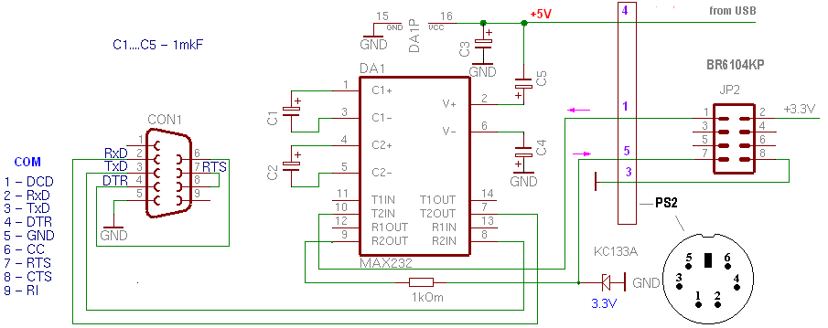
Finally, you connect router through converter to rs232 of PC, set 115200 as speed and if it is alive you should get console output
which may help to diagnose what is wrong. http://adm5120.narod.ru/max232.htm ")
Pinout of JTAG I've seen somewhere on the openwrt site. http://adm5120.narod.ru/ejtag-adm5120.htm 
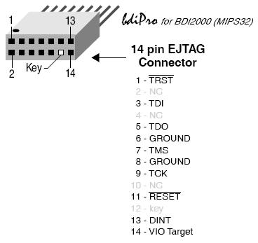

There should be probably description of JTAG-LPT connector and what is needed to do, but I don't have experience with this. 


 Reply With Quote


